
CAR
PRO
Powerblock S-150
CAR products
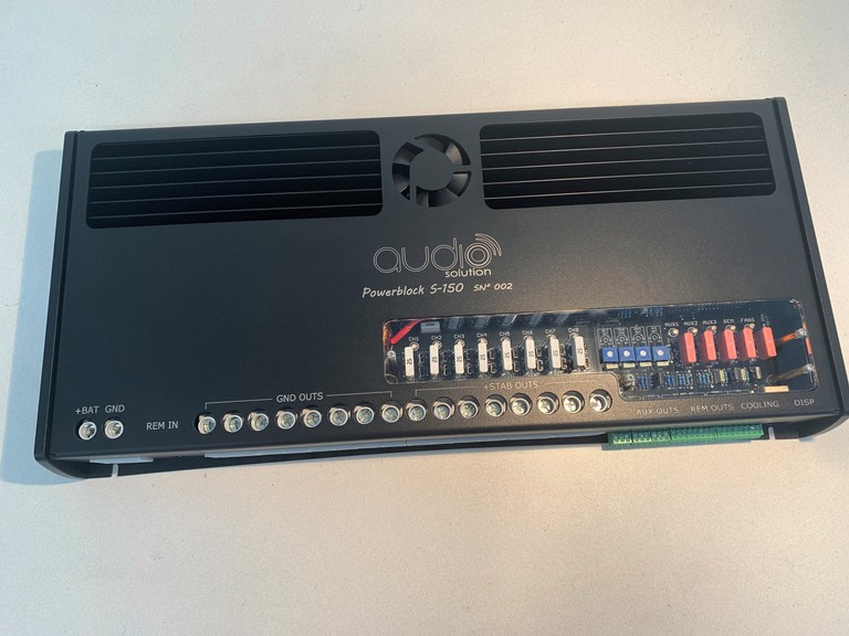
POWERBLOCK S-150
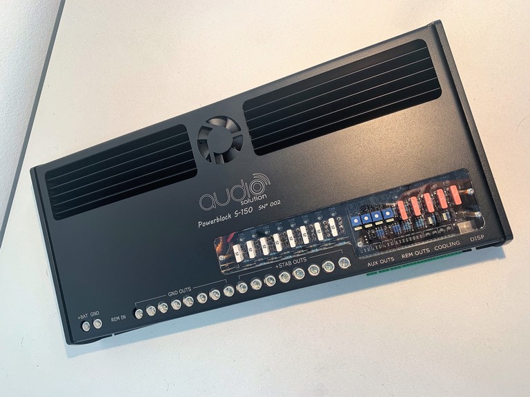
POWERBLOCK S-150 (sistema all-in-one di distribuzione / gestione per elettroniche non stabilizzate )
ITALIANO :
- Ingresso +/GND/REM con 4 fusibili in parallelo (4x40A) per la protezione dell'elettronica
- Sistema di stabilizzazione tensione da 150A continui (300A di picco) con voltaggio di uscita regolabile e ventilizazione forzata sotto termostato
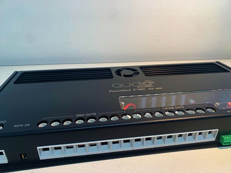
- 8 uscite GND
- 8 uscite + ,ciascuna protetta con 2 fusibili in parallelo
- 8 uscite REM OUT per gli ampli con il loro regolatore di delay
- 3 uscite aux + /GND / REM OUT per utenze , ciascuna con il proprio. I remote di questi 3 aux hanno un loro delay regolabile indipendentemente da quello degli REM OUT dedicati agli amplificatori
- Protezione con fusibile per tutta la sezione REM OUT
- 2 ingressi per sonde termiche e 2 uscite di pilotaggio ventole con temperatura d'intervento regolabile, con fusibile di protezione
- Sistema di diagnostica e led dello stato dei fusibili
- Sistema di spegnimento automatico elettroniche collegate in caso di voltaggio batteria troppo basso
- Gestione di tutte le funzioni tramite microprocessore
- Uscite per cavo dispay da plancia
- Display da plancia (INSPECTOR) per il montaggio V-in , V-out , Temp-1 , Temp-2 , Temp-stab (selezionabile gradi Celsius o fahrenheit) e indicatore "LOW VOLTAGE" e "FAN ON"
POWERBLOCK S-150 (all-in-one for distribution / management system for unstabilized electronics )
ENGLISH :
- + / GND / REM INPUT with 4 fuses in parallel (4x40A) for electronics protection
- 150A continuous voltage stabilization system (300A peak) with adjustable output voltage and forced ventilation under thermostat
- 8 GND outputs
- 8 + OUTPUTS , each protected with 2 fuses in parallel
- 8 REM OUT for amps with their own delay control
- 3 aux OUTPUTS + / GND / REM OUT for users, each with its own. The remotes of these 3 auxes have their own adjustable delay independently from that of the rem out dedicated to the amplifiers
- Protection with fuse for the whole REM OUT section
- 2 INPUTS for thermal probes and 2 piloting outputs with adjustable intervention temperature , with protection fuse
- LED diagnostic system for the status of the fuses
- Electronic automatic shutdown system connectedDin case of too low battery voltage
-Management of all functions by microprocessor
- OUT PUT for dashboard display cable
- Dashboard display ( INSPECTOR) for monitoring V-batt , Temp-1 , Temp-2 (selectable degrees Celsius or Fahrenheit) and "LOW VOLTAGE" and "FAN ON" indicator
ISTRUZIONI PER UNA CORRETTA INSTALLAZIONE :
- Rimuovere il fusibile di protezione del sistema audio posto tra la batteria e il Powerblock
-Rimuovere il coperchio in plexiglass per avere accesso alle slot dei fusibili
-Cablare l'intero sistema avendo cura di installare all'interno del Powerblock i fusibili di valore idoneo in base alle elettroniche installate
- Porre un tester (settato su VDC) con i puntali sulla morsettiera di ingresso + e GND del Powerblock (la tensione letta dovrebbe essere prossima allo zero dato che i condesatori saranno totalmente scarichi)
-Porre la resistenza di carica fornita in dotazione al posto del fusibilie di protezione generale del sistema (si noterà che la tensione letta dal tester inizierà a salire)
- Quando il tester indicherà una tensione prossima ai 12 VCD rimuovere la resistenza e sostiturla con il fusibile. Rimuore quindi il tester.
-Rimontare il coperchio in plexiglass
-Tale operazione va ripetuta per precauzione ogni volta che il sistema audio viene scollegato dalla batteria del veicolo
INSTRUCTIONS FOR CORRECT INSTALLATION:
- Remove the audio system protection fuse located between the battery and the Powerblock
-Remove the plexiglass cover to gain access to the fuse slots
-Wire up the entire system, taking care to install the fuses of the right value on the basis of the electronics installed inside the Powerblock
- Place a tester (set to VDC) with the tips on the INPUT terminal block + and GDN of the Powerblock (the voltage read should be close to zero since the capacitors will be totally discharged)
- Place the supplied charge resistor in place of the system's general protection fuse (you will notice that the voltage read by the tester will bwgin to rise )
- When the tester indicates a voltage close to 12 VCD, remove the resistor and replace it with the fuse. He then removes the tester.
- Refit the plexiglass cover
-This operation must be repeated as a precaution every time that the audio system is disconnected from the vehicle battery